









Software development
and consulting in
mining & geomechanics

Trusted by leading mining companies

PROROCK 2.0

This is a newly emerging software for solving geotechnical problems having the opportunity to model rock mass failure and dynamic processes. The powerful mathematical tool of the software models destructive processes with all degrees of deformation, both elastic and occurring with discontinuities, fragmentation and subsequent substitution of fragmented rockmasses.
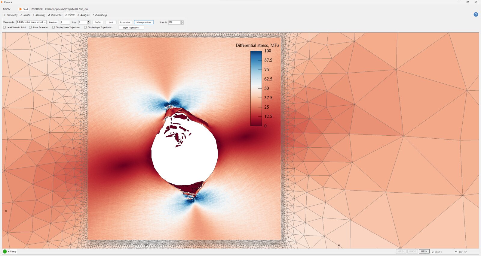
Simulation result: differential stresses around the opening
Simulation result: stresses around the opening, view 2
Output
Viewmode
Accelerate your FDEM simulations
Powered by CUDA and optimized for performance, our solver brings simulation times down from hours to minutes.
Rock Fracture and Fragmentation
FDEM captures the full failure process as cracks form and open, the rock breaks apart, and the resulting blocks move and interact.
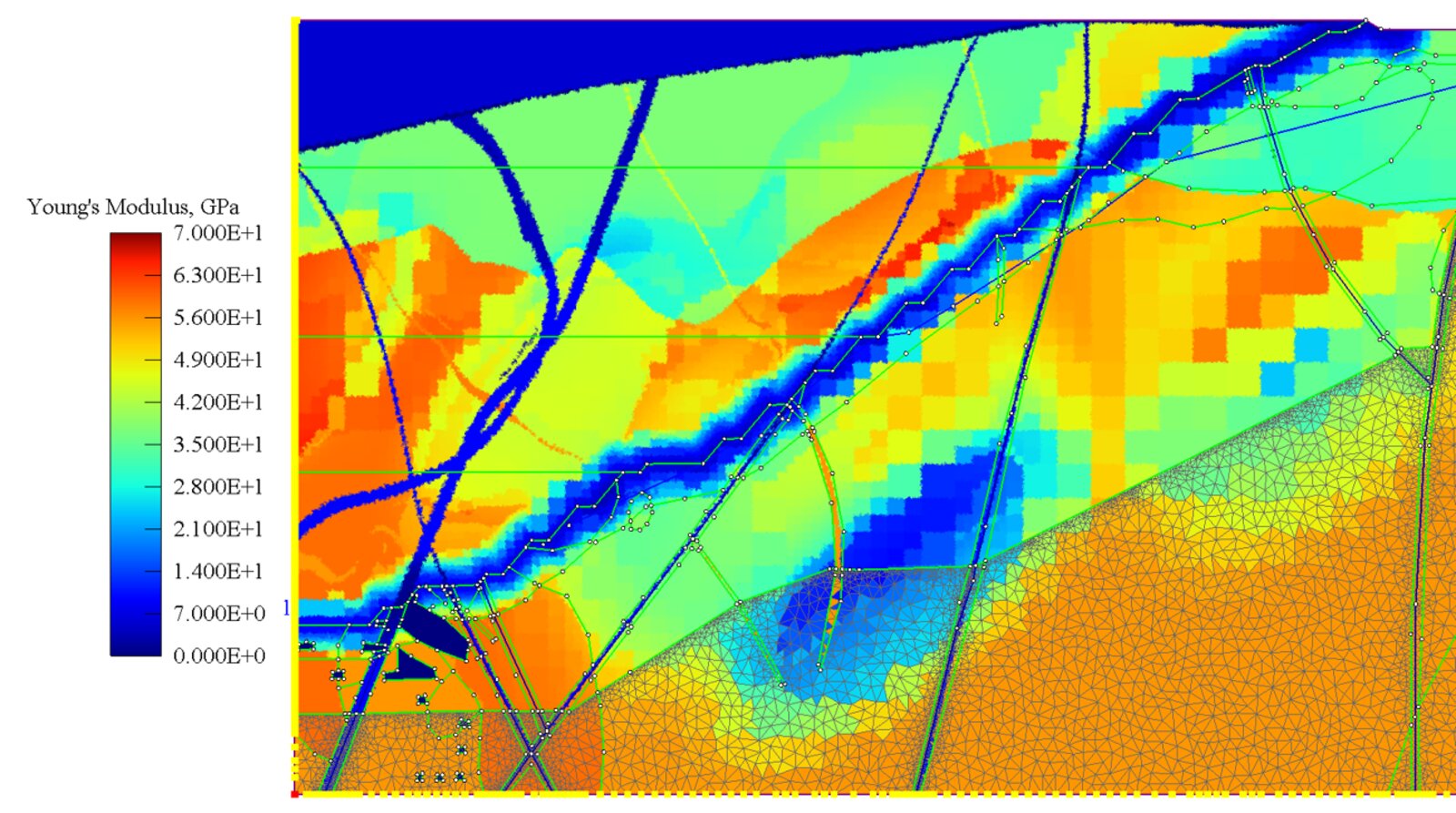
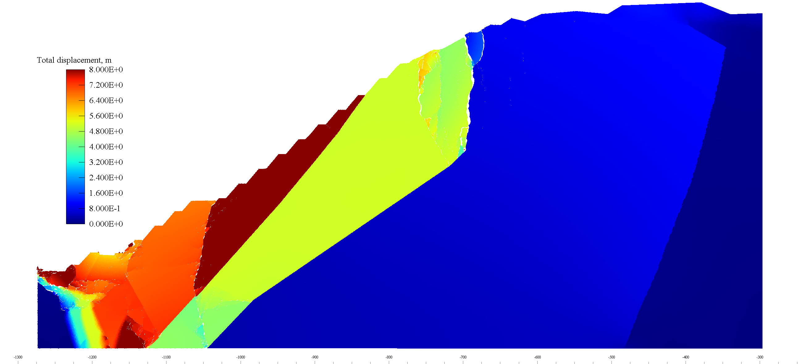
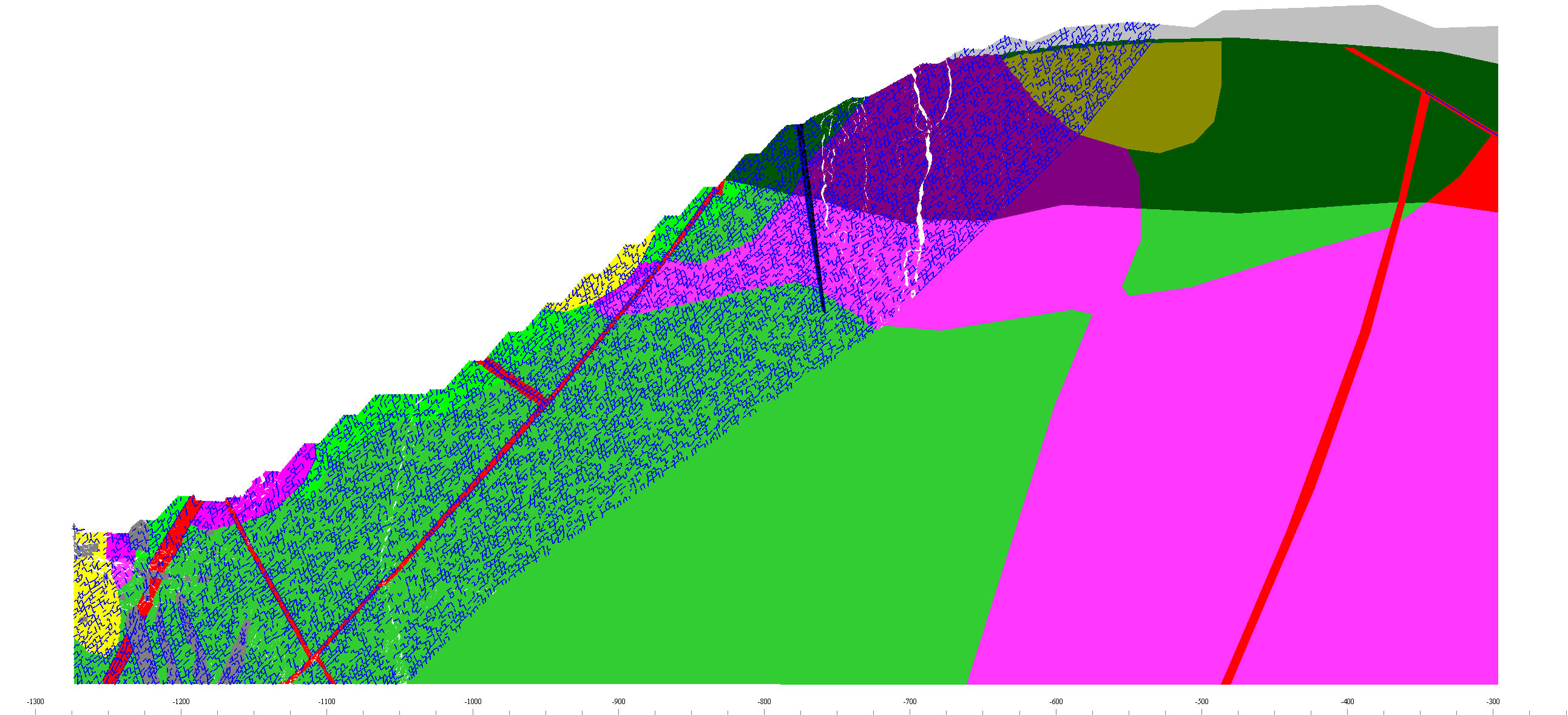
Slope model: Young's modulus by engineering-geological unit
Block Model Import
Import an existing block model into Prorock and use it as the starting point for your geomechanical simulations.
Watch tutorial

Key features

  • Takes into account rock deformation and strength properties, post-peak plastic deformation, DFN, in-situ stress, and external loads
  • Generates a mesh optimized for FDEM analysis
  • Automatically detects and corrects geometric errors (Autofix)
  • Simulates excavation, backfilling, and extraction processes
  • Defines discontinuities, tectonic faults, fractures, and anchor systems
  • Provides comprehensive visualization and export of results in tabular form (txt, csv)

Magicore
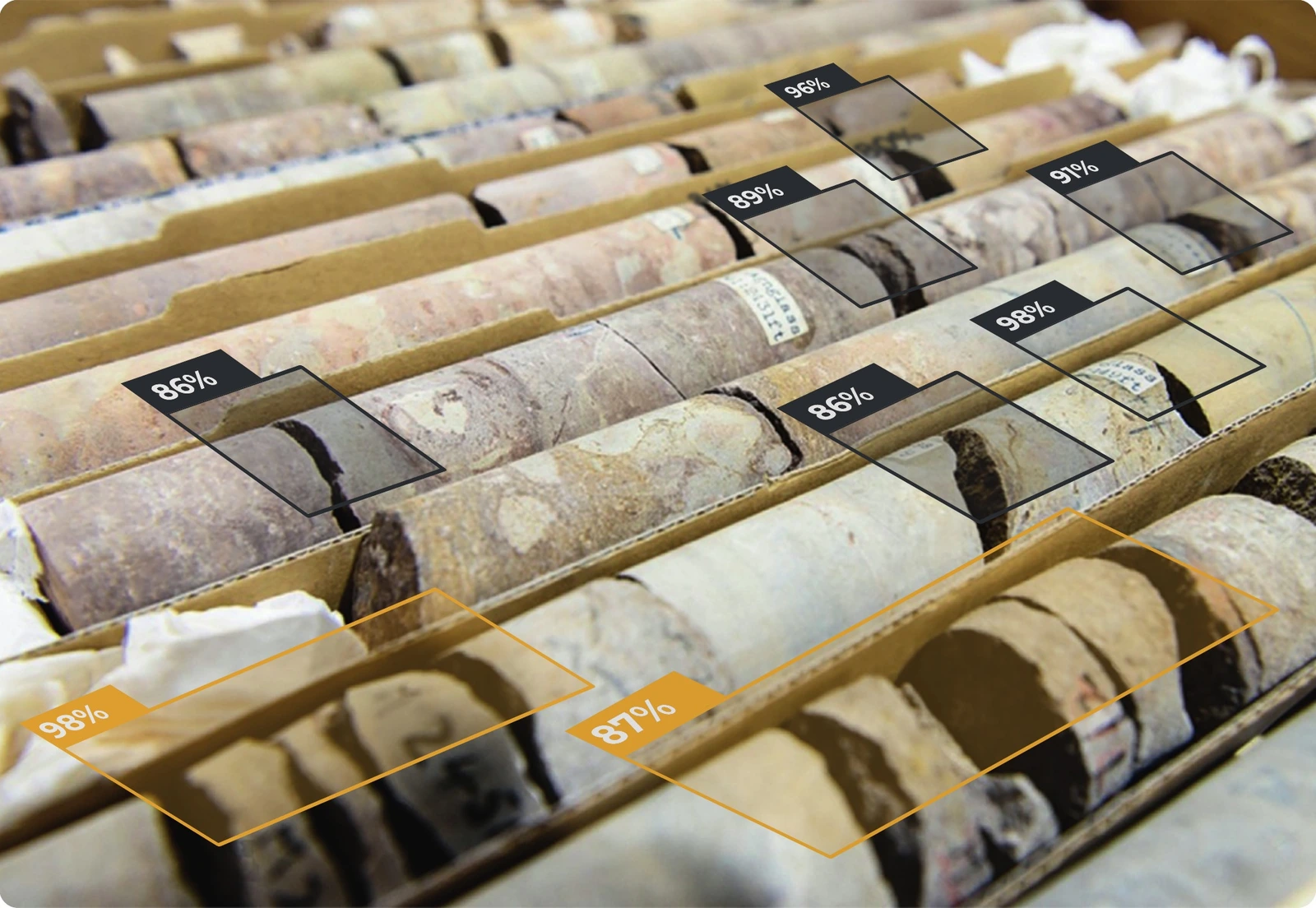
A web service for automatic geotechnical core logging using neural networks

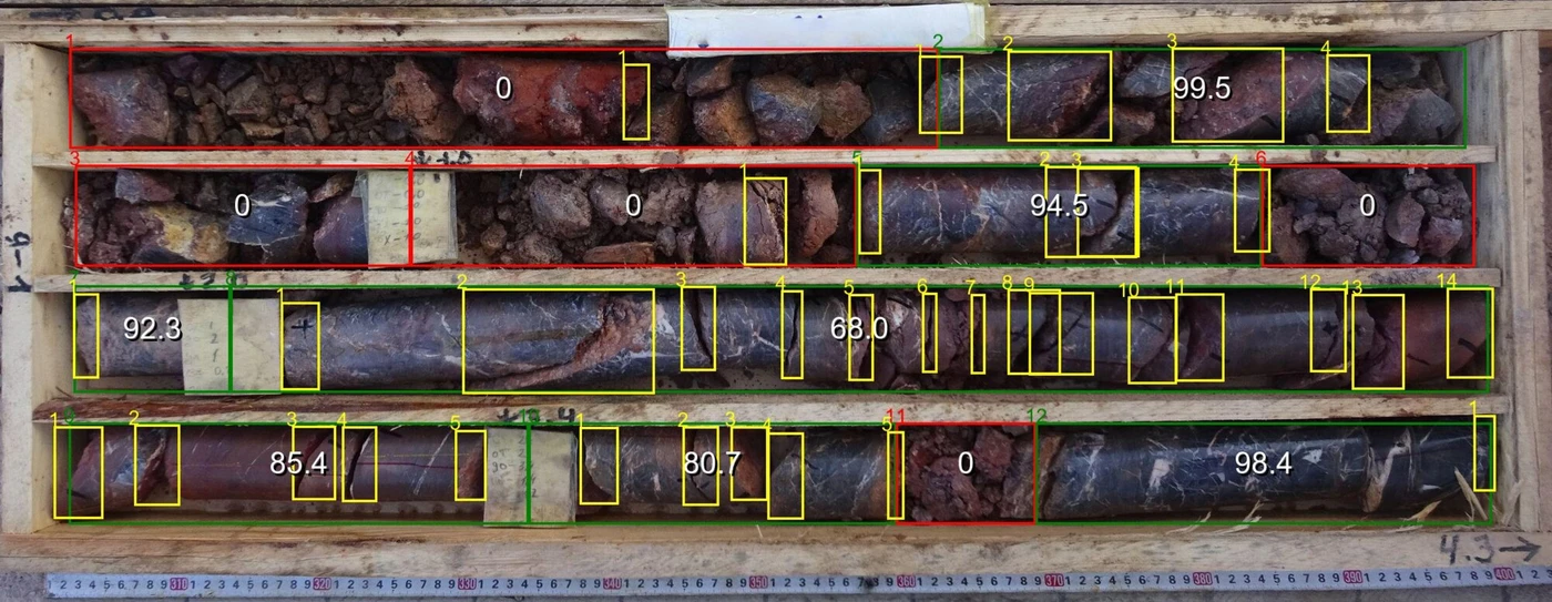
Core boxes with RQD values detected by Magicore

Applications

  • Acceleration of geotechnical core logging process
  • Audit of geotechnical core logging prior to acceptance
  • Processing of archival core photographs
Time saving54 boreholes processed in 2 days
High accuracyExclude errors and loss of quality when transferring data to Excel in the field
ConvenienceSimple and intuitive interface
AI technologiesUses computer vision and machine learning with the possibility of continuous improvement
Processing speed
1000 meters/hour
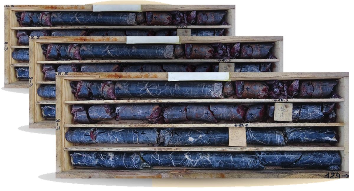
Stack of processed core box photos
In 2 days
Processed boreholes54
Average length of boreholes100m
Fractures identified34706
Intervals identified9121
Avg. length of intervals58cm

Features

  • Binds photos of the core by depth
  • Identifies artificial and natural fractures with 77% accuracy
  • RQD and FF/m with 93% accuracy
  • Identifies geotechanical intervals
  • Calculates the angle α for discontinuities
  • Provides Excel with structural and interval documentation

How It Works?

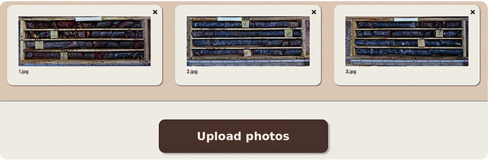
  1. 1Visit magicore.ru and upload a core photo taken with your phone

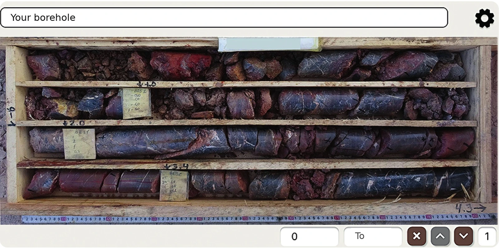
    Uploading core photos in Magicore
  2. 2Set the depths of the core box for image scaling

    Setting core box depths
  3. 3Customize data visualization and process with neural networks

    Neural network results on a core box photo
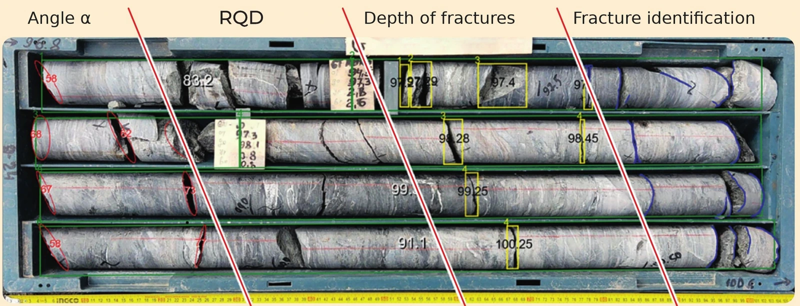
  4. 4Our algorithm takes care of everything for you, delivering results as photos and Excel tables, all conveniently packed into a single ZIP file

Core box annotated with angle α, RQD, depth of fractures and fracture identification

Digger Slope

Digger Slope – software for analyzing and optimizing slope stability, enabling the assessment of engineering risks and minimizing overburden removal costs

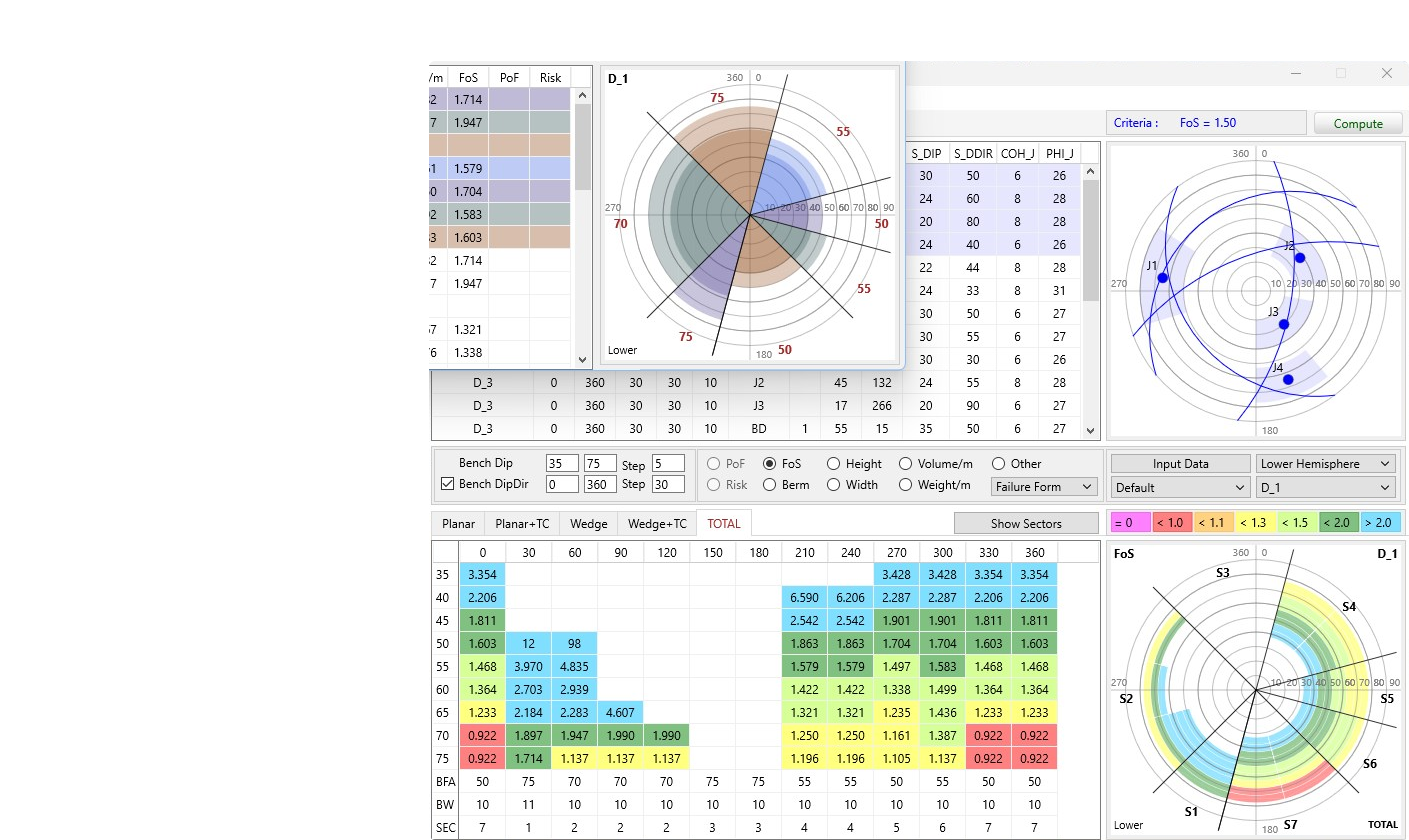
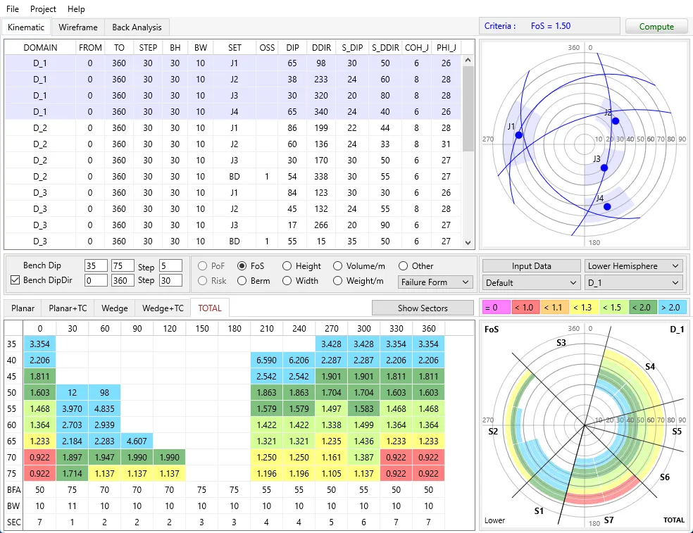
Digger Slope: sector table, factor of safety and stereograms
Kinematic analysis
4 failure modes
PlanePlane
Plane + tension crackPlane + tension crack
WedgeWedge
Wedge + tension crackWedge + tension crack

Features

  • Planar, wedge and toppling failures, plus automatic search for tension cracks
  • Deterministic and probabilistic stability analysis
  • Domains: structural zoning and lithology
  • Hydrogeology, seismicity, external loads and plan-view curvature of the pit wall
  • Safety berm design for the equipment in use
  • Back-analysis of cohesion and friction angle from recorded failures

Cases

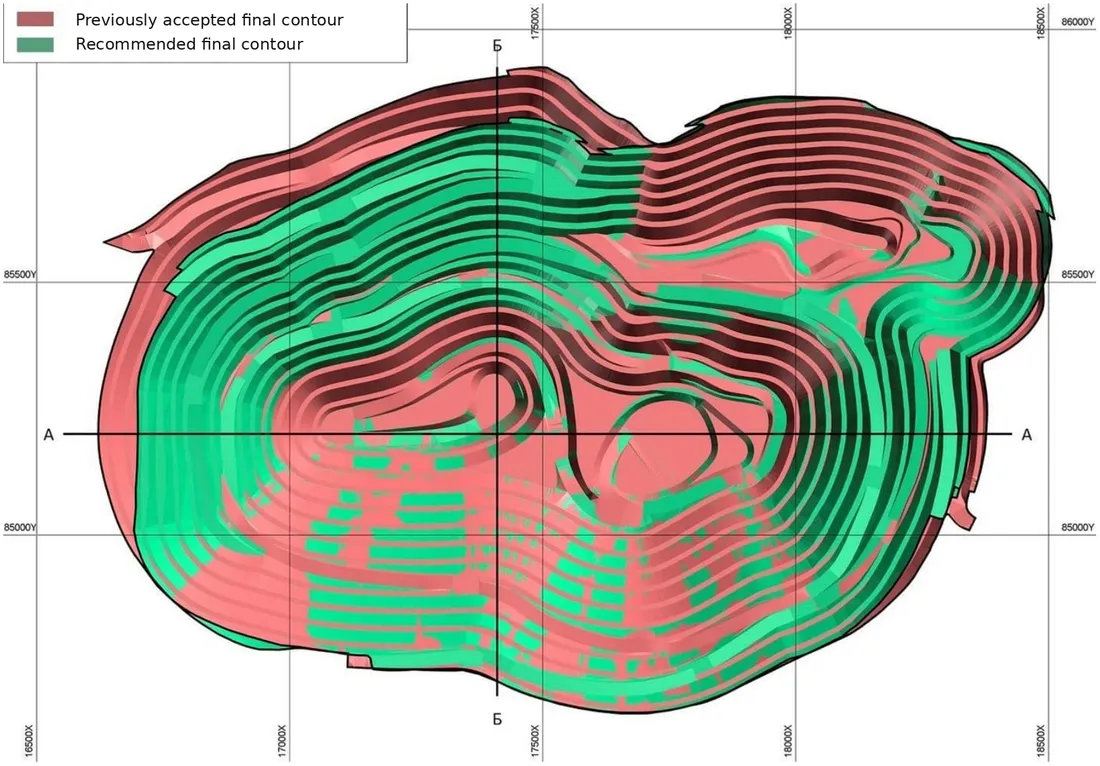
Uzbekistan · open pit
Open pit mine in Uzbekistan
+7°steeper pit slope
16M m³less overburden
~$38Msaved at $2.38/m³
Pit plan: previously accepted vs recommended final contour
Plan: previously accepted (red) vs recommended (green) final contour
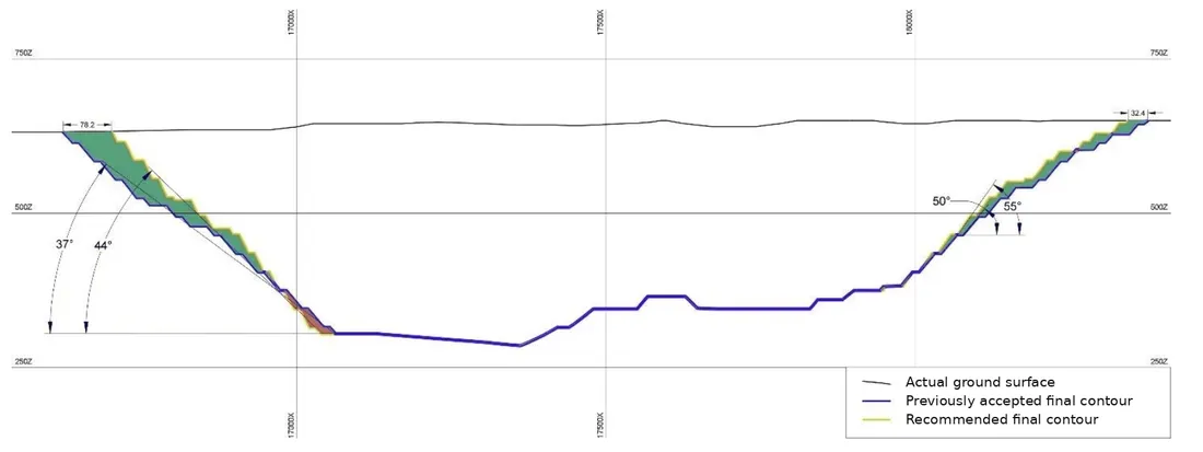
Russia · gold
Gold deposit in Russia
  • Multiple failures in the central sector of the open pit were prevented
  • Stability of the pit slope in the western sector was ensured
Section A–A: overall slope angle increased from 37° to 44°
Section A–A: overall slope 37° → 44°
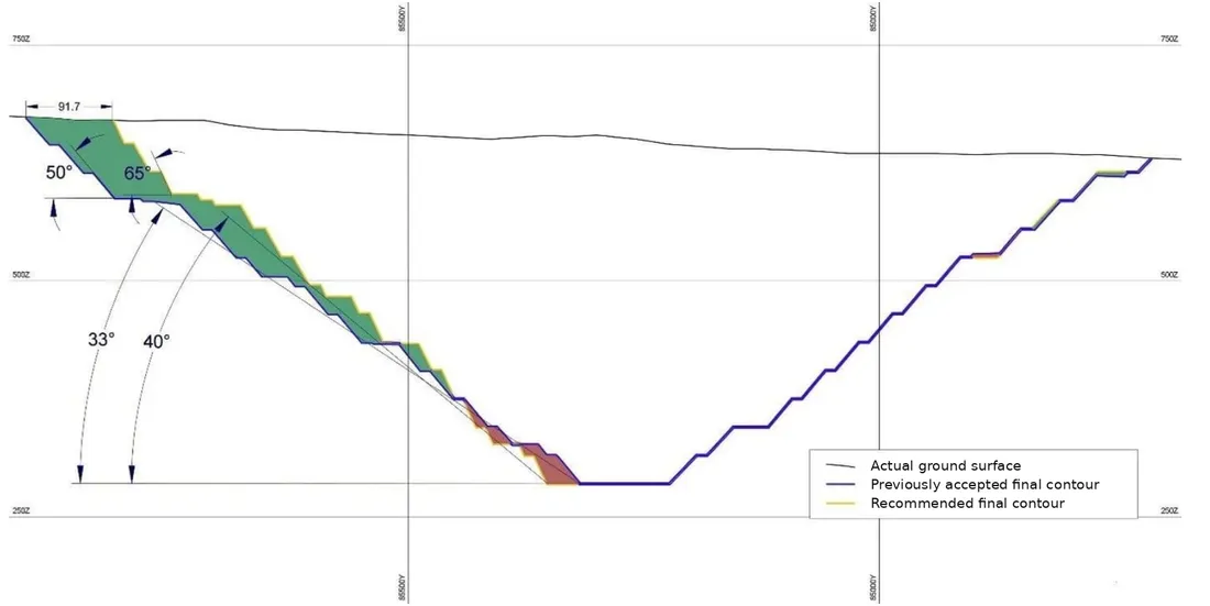
Kazakhstan · copper
Bench optimization at a copper deposit
  • Adverse slope orientations were eliminated, which increased bench stability
Section B–B: overall slope angle increased from 33° to 40°
Section B–B: overall slope 33° → 40°

How It Works?

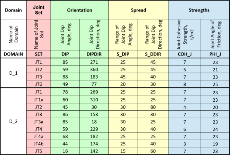
  1. 1Prepare the input data: joint set properties and domain parameters

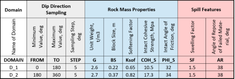
    Joint set properties by domainDomain parameters
  2. 2Enter the domains: joint sets, slope geometry, hydrogeology, seismicity and loads. Stability is calculated automatically over a grid of slope orientations.

    Domain input and stereogram in Digger Slope
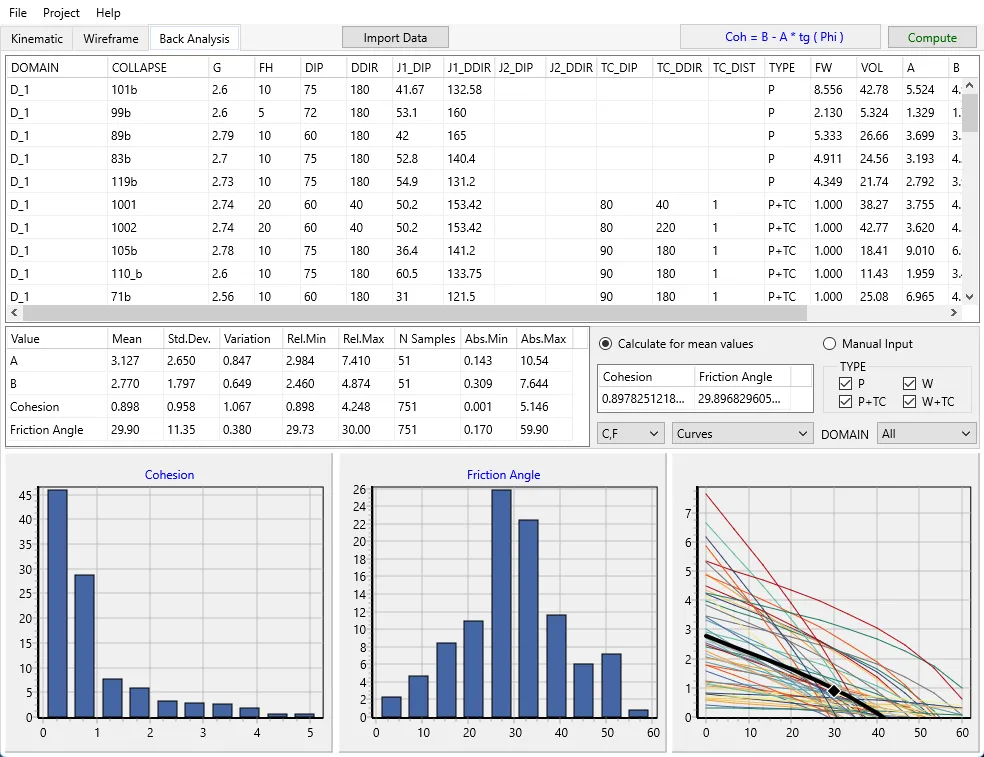
  3. 3Calibrate the model with back-analysis of recorded failures

    Back-analysis: histograms of cohesion and friction angle
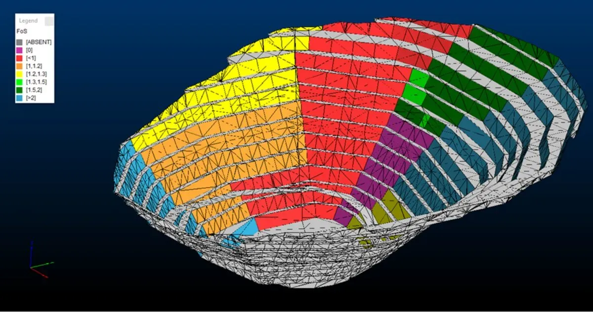
  4. 4Get the Kinematic Map of the Pit: slope angles, berm widths, factor of safety, probability of failure and predicted failure volumes

    Kinematic map of the pit: factor of safety on the 3D wireframe

ScientiaJoints

A free Blender plugin for digital fracture mapping on 3D outcrop models

Latest update · Blender 5.2
  • New tools: polygon and trace length measurement
  • Automatic snapping to face, edge and vertex
  • Layer management by code
  • Measurement labels in 3D and export
  • Bug fixes and better performance

Key features

Mapping on 3D modelsMeasure fractures directly on photorealistic outcrop models
Measurement toolLength, azimuth, dx, dy, dz from 2 points; angle and area from 3
Polygon measurementPlane fitted to 3+ points with area, orientation and accuracy
Trace lengthLength of visible fracture traces, including curved outlines
Geometry snappingSnap to face, edge or vertex without holding CTRL
Layer managementColors and visibility by code for every measurement
Labels in 3DCode, name, length, azimuth or area shown right in the scene
Stereonet and exportJoint-set statistics, spacing histogram and CSV export

NUR Extensometer

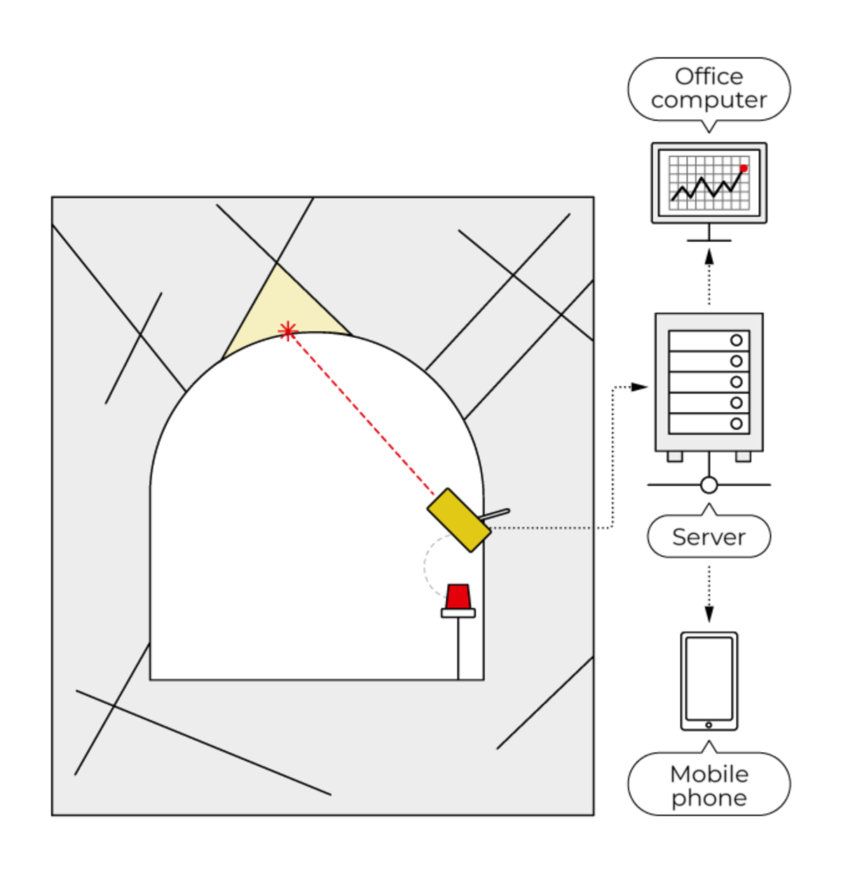
NUR automatically monitors crack opening and rock mass movement on pit slopes and in underground openings. The device works autonomously, transmits data over GSM and provides early warning when deformation accelerates to dangerous rates.
NUR in an underground opening: measuring to the roof, data sent to the server and app
Underground
Convergence
Underground openings
Doweled to the concrete lining and rotates 360°. Measures convergence of openings and monitors rockfalls from the roof and walls.
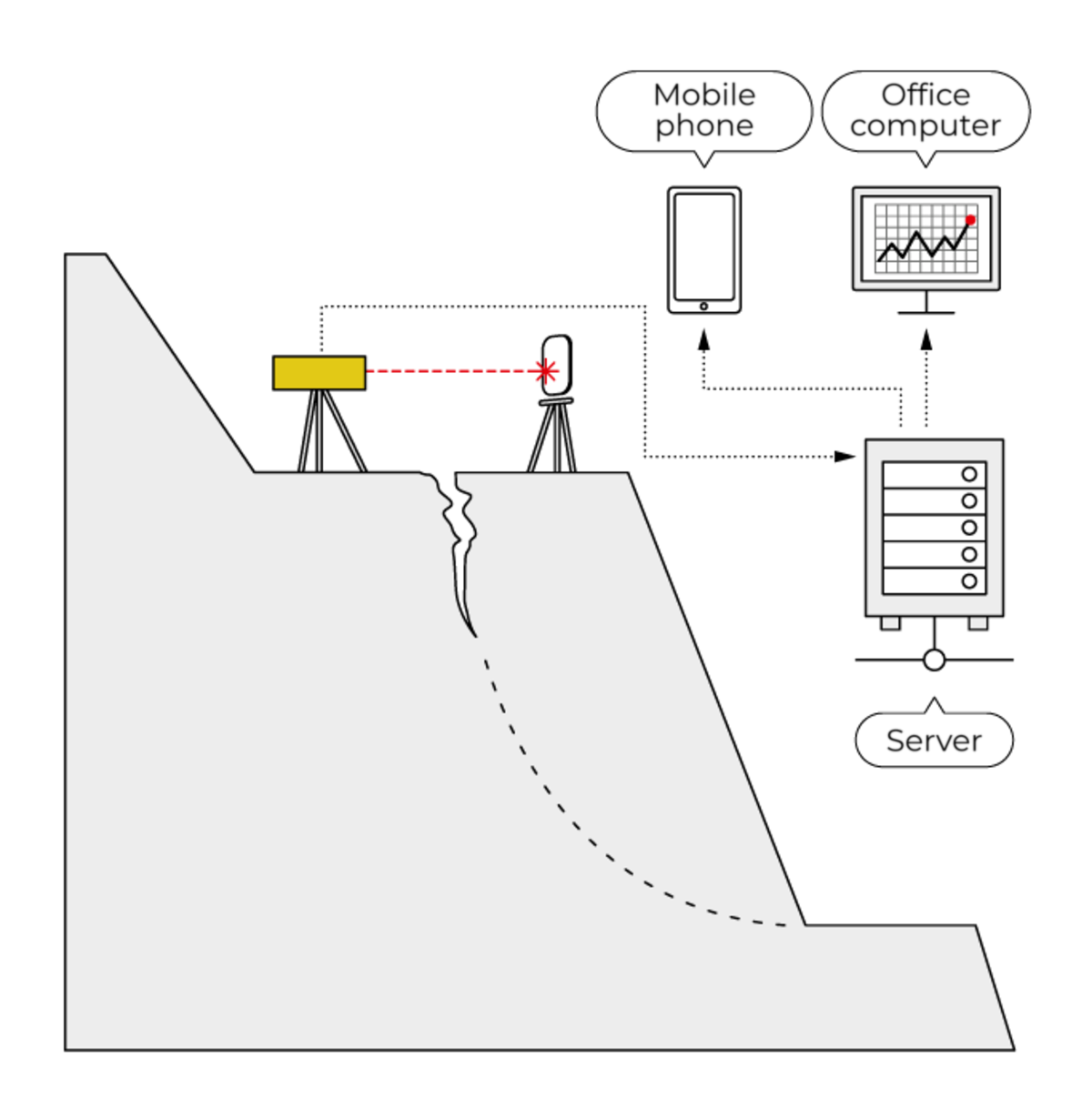
NUR on a pit slope: laser measurement to a crack, data sent to the server and phone
Open pit
Cracks · fractures
Pit slopes
A tripod anchored in the ground. Monitors mining-induced cracks and crack opening, and picks up movement early, before a failure.
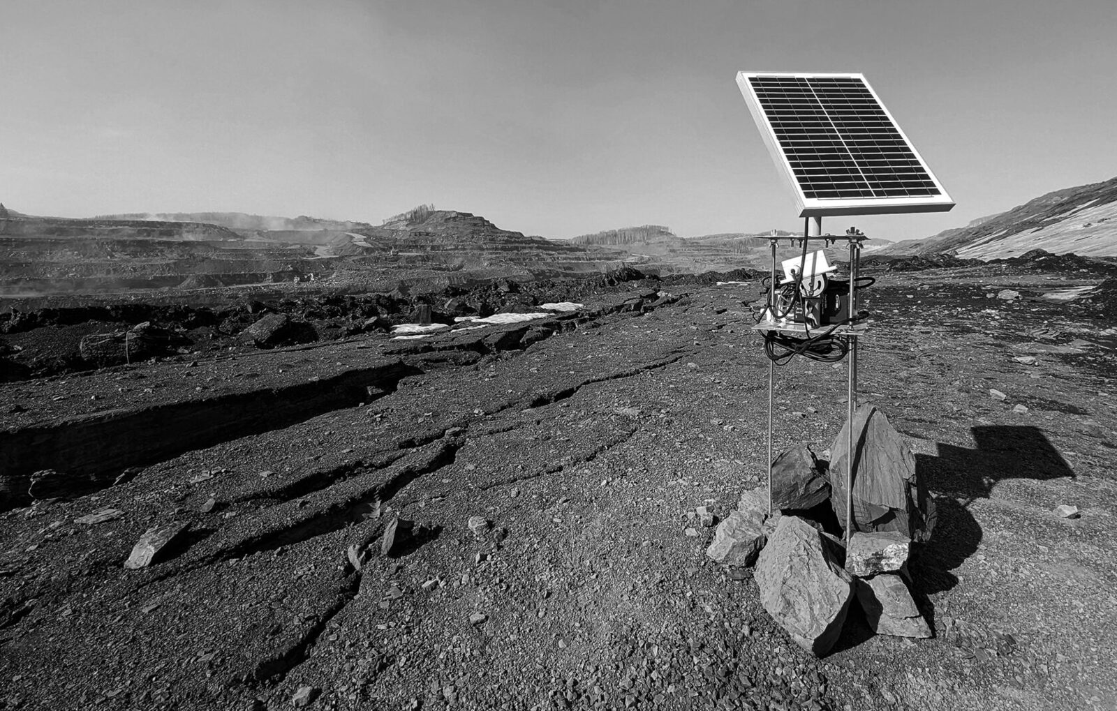
Autonomous NUR station with a solar panel on an active pit slope
Autonomous
Solar · GSM · IP65
Autonomous field operation
Solar powered, 144 Wh battery: from 9 days (a reading every 10 s) to a year (every 10 min). Data goes over GSM, with Telegram, SMS and email alerts when critical rates are exceeded.
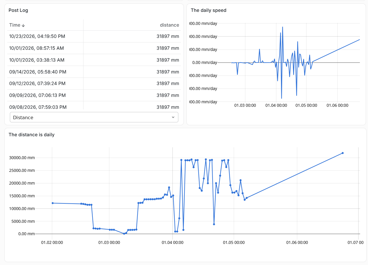
NUR online dashboard: post log, daily speed and daily distance charts
Online monitoring dashboard
Every reading goes to the web dashboard: the post log, daily displacement speed and distance charts for each station.
Mining-induced cracks
Monitoring of mining-induced cracks and crack opening.
Rockfalls
Rockfall monitoring on pit slopes and in the walls and roof of underground openings.
Convergence
Convergence of underground openings.
Failure prediction
Displacement rates make it possible to predict when a failure will occur.
Measurement rate
Configurable, from 1 s⁻¹; online data latency of about 1 s.
Installation
A dedicated mount that locks in place and rotates 360°.
Field tests
Tested in open pits; not yet tested underground.

Joint Explorer

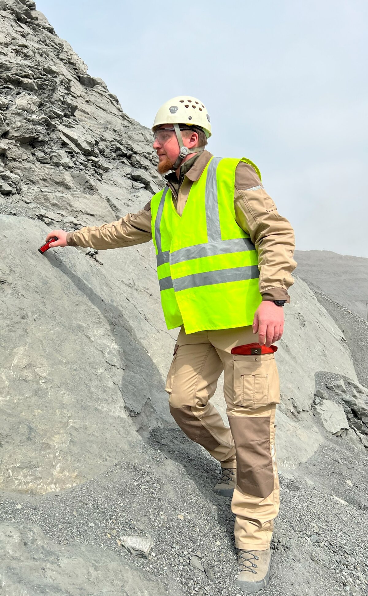
The Joint Explorer electronic compass is a dedicated instrument for measuring the dip and dip direction of joints and faults. Unlike an analog compass, it lets you take more readings in less time. The dedicated JointExplorer mobile app provides preliminary field analysis of the device data and generates export tables for every measurement station. The device has passed internal testing on many completed geomechanics projects.
Joint Explorer orientation measurement on a pit slope
Mapping
Dip & Dip direction
Faster than an analog compass
More orientation readings in less time, right at the outcrop, with no notebook or protractor.
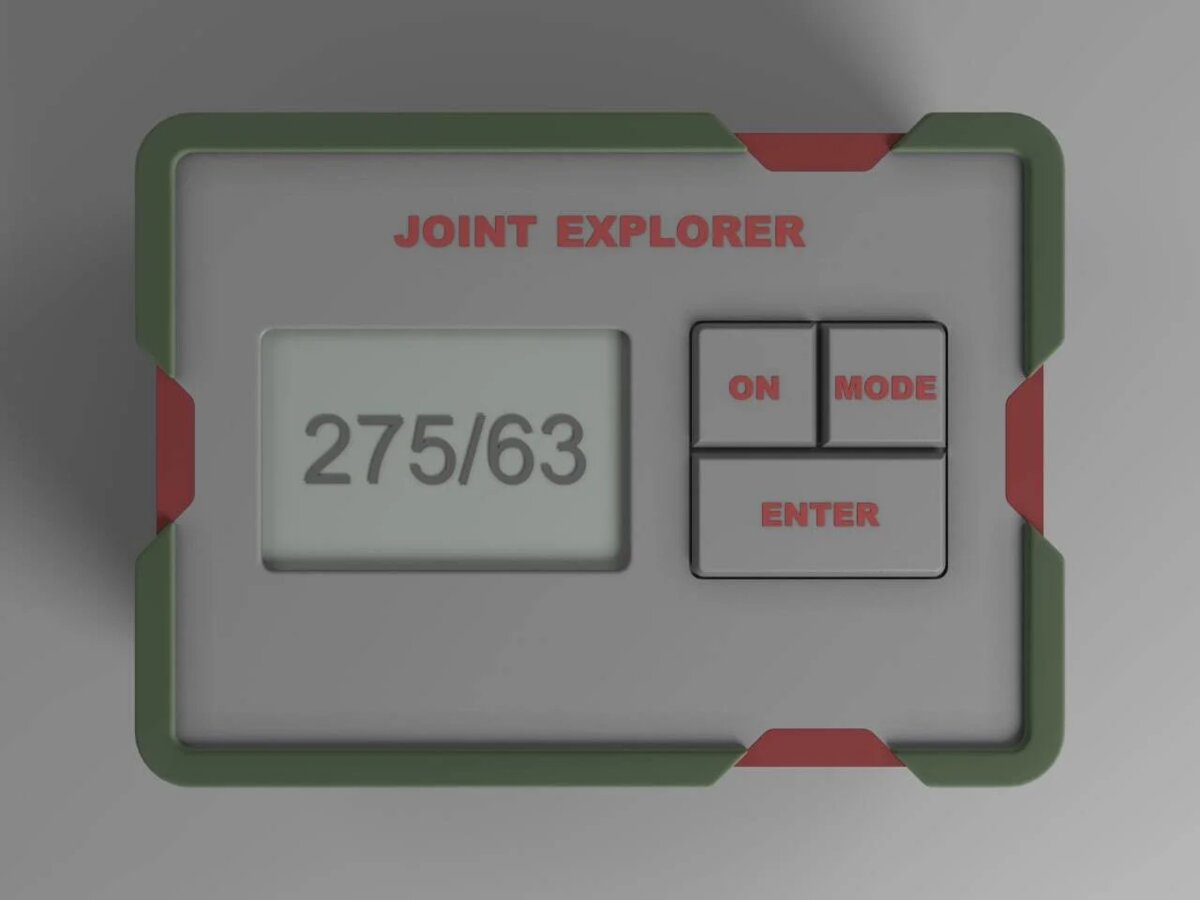
Joint Explorer device showing 275/63
Compact case
Electronic geological compass
Dip and dip direction of joints and faults at the push of a button.
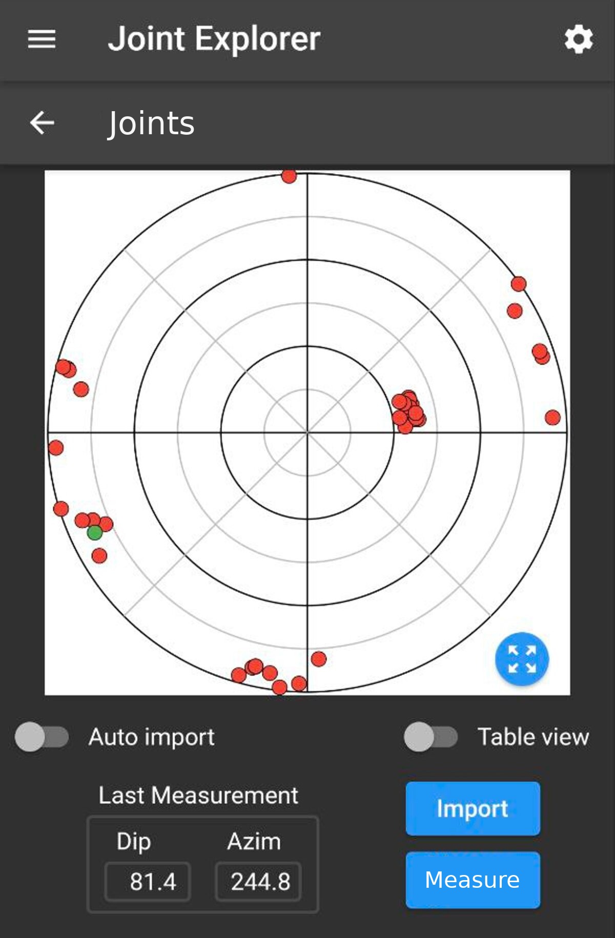
Joint Explorer mobile app: measurement stereonet
App
Stereonet
Mobile app
Field analysis with a stereonet and export tables for every measurement station.

Key features

Dip and dip directionFor joints and faults.
Mobile softwareThe dedicated JointExplorer app for mobile devices.
More readingsMore readings in less time than with an analog compass.
Field analysisPreliminary analysis of the device data.
Table exportExport files for every measurement station.

Get in touch

We'll get back to you within one business day to answer your questions and agree on next steps.

By clicking the button, you consent to the processing of your personal data and agree to the privacy policy.